

6347
A Methodology to Guide Industrial Explosion Safety System Design - Part 1
07/31/2018
It is essential that suppliers and users of explosion protection products and systems fully understand the efficacy and reliability upon demand of such products and systems. A systematic methodology for quantifying residual risk in the context of installed explosion mitigation has been described by the authors. This methodology explicitly accounts for the two principal mechanisms of failure:
- failure of the hardware;
- ineffective explosion protection (e.g. the reduced explosion pressure of a suppressed or vented explosion occurrence is greater than the pressure shock resistance of the vessel).
This paper considers the challenges faced in determining a meaningful residual risk datum for a processing plant. In particular it sets out the importance of the implicit assumptions and shows, by reference to process industry examples, the benefits of electing a systematic means of ascribing explosion protection security.
In order to quantify the residual risk of safety system failure in the practice, an overarching understanding of the efficacy of explosion mitigation means, system design, safety factors (both implicit and explicit) and the consequence of flame propagation between connected vessels, is of paramount importance. existing explosion protection design guidance is invariably constructed around test data that have taken the premise that central ignition of a homogeneous and turbulent optimum fuel concentration in a closed vessel represents the worst case scenario. However this is not necessarily the most appropriate baseline for ascribing the risk of an unmitigated explosion occurrence.
This work demonstrates that explosion protection “trade off” decisions, design safety factors, and the design premise itself all contribute to the “relied upon” safety integrity of an industrial process. With this understanding and the adoption of a systematic methodology to determine a residual risk datum, practitioners can make more informed and cost effective design decisions, leading to enhanced overall process safety.
Description of the Calculation Methodology
A method for calculating residual risk of safety system failure has been set out previously by the authors [Ganguly, 2007], and the pertinent mathematical derivations are fully explained elsewhere [Date, 2008]. In this paper we present a brief description of the model and its implicit assumptions, using the same nomenclature as previously, for ease of reference.
Our intention is to demonstrate the value of such an approach to improve overall process safety. The process plant and its protection system are represented by a connected, bi-directional graph (West, 2001). In this architecture each plant item in the process is represented as a vertex, whereby edges between vertices represent possible flame paths (i.e. the connecting duct-work).
Assumptions
- We use the probability of an unmitigated explosion in a given unit of time as a proxy for residual risk.
- All ignition locations within each plant item are equally probable.
- An unmitigated explosion (failure) is defined as any occurrence where the reduced explosion pressure of a suppressed or vented explosion is greater than the pressure shock resistance of a plant component.
- Given an ignition event, an unmitigated explosion is assumed to occur when any one component of the protection system fails, be it a vent panel, detector, suppressor or control Consideration of component redundancy and the impact on residual risk is fully tractable, but is not addressed further here.
- We consider the consequence of all failures in reality, not all failures will lead to a catastrophe, however by comparing all failures equally we are still able to compare different safety system designs.
- We only consider the probability of failure of the plant item that has the ignition event and those directly connected to it. The model is not bound by this assumption – extension to second order connectivity is tractable, but of negligible significance.
Definition of model parameters
Each vessel or plant item i (vertex i) within the process plant, together with its associated explosion protection system is characterised by a set of parameters which are described in this section.
- QE(i) is the ignition probability in vessel i. For a given process plant and over a given unit of time we assume that åi QE(i) = 1, e. that there will be one ignition occurrence somewhere in the process plant.
- Pred(i, j) is the reduced explosion pressure in vertex i following an ignition in vertex j. Ps (i) is the pressure shock resistance of the vertex i. The values quoted for Pred(i, j) and Ps (i) are intentionally very conservative to represent the worst case and to err on the side of safety. However, excessive safety factors will result in unrealistic values for the computed residual risk. We have elected to use a standard deviation of 10% of the mean value for both Pred(i, j) and Ps(i), and that the values specified are the two standard deviation limit values.
- Qvessel(i, j) represents the probability that the explosion protection hardware does not fail, but the reduced explosion pressure is still higher than the pressure shock resistance of the vessel:
Qvessel(i, j) = P[Pred (i, j) - Ps(i) > 0] (1)
This allows us to represent the proximity of Pred (i, j) to Ps(i) in the system design and account for any intentional design safety factors in our computation of residual risk.
- in a similar manner, we can define a set of parameters which relate to the efficacy of explosion isolation barriers. We define tb(i, j) as the time taken from ignition for the isolation barrier to be established between vessels i and j. implicit in tb(i, j) is the time taken to detect the explosion (whether via optical or pressure detection) and the actuation time of the isolation hardware such that flame cannot pass. tf(i, j) is the time taken for the flame front to arrive at the barrier location, and will be the summa- tion of the time taken for the flame to enter the duct from the ignition location, and the time for the flame to transit the duct to the barrier Thus for efficacious explo- sion isolation tf(i, j) > tb(i, j). once again the specified values for these parameters are very conservative and we apply the same assumptions as with the pressure parameters, taking a standard deviation of 10% of the mean and that the specified values are the two standard deviation limit valuesQbarrier(i, j) represents the probability that the isolation hardware is actuated and the barrier established, but the barrier is deployed too late and flame passes into the adjoin- ing vessel:
Qbarrier(i, j) = p[tb(i, j) - tf (i) > 0] (2)
- Qs (i, j) is the probability of flame propagation between connected vessels i and j which then leads to an enhanced explosion in j. This of course will be sensitively dependent on the geometric configuration (relative vessel sizes, duct length and diameter, process flow direction and velocity) together with the fuel properties and the explosion mitiga- tion means employed on both the source and connected vessels.
- The total flame propagation probability from vessel i to j, Qs (i, j), can be computed by summing the probability due to hardware failure (Qh(i, j)) and the probability due to late activation of the barrier 1 - (Qh(i, j)) ´ Qbarrier(i, j)) to give:
Qs (i, j) = Qs (i, j) ´ [Qh(i, j) + (1 - Qh(i, j)) ´ Qbarrier(i, j)] (3)
- Qh(i, j) can be calculated with knowledge of the mean-time-between-failure of the hardware components combined in an appropriate manner to represent the configuration of the protection system [Date, 2008, Ganguly, 2007].
When all of the above parameters have been specified for each vessel and connec- tion, we have all the necessary information to compute the residual risk of safety system failure.
Computation of residual risk
The risk of failure of any vessel i due to ignition in vessel j, is denoted Ri,j and can be computed as the sum of the risk of hardware failure, Qh(i), and the risk of inadequate protection, (1 - Qh(i)) ´ Qvessel(i, j):
Ri, j = Qh(i) + (1 - Qh(i)) ´ Qvessel(i, j) (4)
once again, Qh(i) can be calculated with knowledge of the mean-time-between- failure of the pertinent hardware. We can now calculate the risk of failure in any vessel i due to an ignition in the same vessel or any vessel directly connected, zi, as:
z = Q (i) ¥ R + ÂQ ( j) ¥ (1 - R ) ¥ Qs ( j,i) ¥ R (5)
i E i,i E j, j iŒFj
where Φi, denotes the set of vertices adjacent to vertex j.
Example computation of residual risk
To illustrate this calculation methodology and demonstrate its use in guiding explosion safety system design, we consider the example of a simple milling and collection process (see Figure 1), where explosible dust represents the principal hazard [eckhoff, 2003]. in this process a granulated chemical product is fed into a Grinder, and the product fines are pneumatically transported to a Storage Hopper. residual dust from the Cyclone is extracted by a Bag-Filter before the process air is returned to the atmosphere. The Bag Filter and the Storage Hopper are protected by explosion suppression systems, whilst the Grinder and Cyclone are protected by appropriately sized explosion vent panels. in this example, a fast-acting explosion isolation valve has been installed to minimise the risk of flame propagation from the Grinder to the Cyclone.
First we must ascribe ignition probabilities (QE(i)) for the four vessels in our example process. This will of course be dependent on the material being processed (e.g. explosibil- ity, concentration, minimum ignition energy etc.) and the nature of the process. in order to attain representative values we have taken literature data [Jeske, 1997] and organised it so as to be able to quote typical ignition probabilities for generic plant processes. part of the organisation of this data involved excluding ignition sources that were external to the process, such as fire, and then grouping ignition sources that were pertinent to generic plant processes and then normalising these probabilities. Although this methodology is a simpli- fication of the practice, it is based on real data and serves the purpose of providing represen- tative ignition probabilities. The QE(i) values determined for each vessel in our example are shown in Table 1. Also shown in Table 1 are the vessel strengths, Ps(i), and the reduced
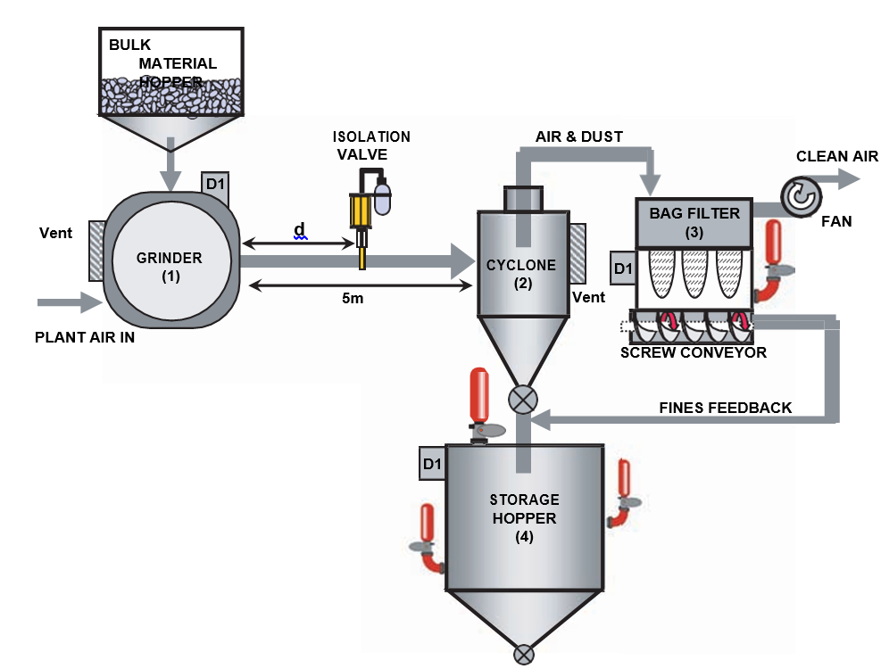
figure 1. Schematic representation of an example milling and collection process. The grey arrows represent material flow through the plant. d represents the installed distance of the isolation barrier from the Grinder
table 1. ignition probabilities, QE(i), pressure shock resistance, Ps(i), reduced explosion pressure, Pred(i, i), and the probability that the explosion protection hardware does not fail, but the reduced explosion pressure is still higher that pressure shock resistance of the vessel, Qvessel(i, i), (calculated using equation 2) for each vertex in the example milling and collection process
|
plant item |
Vertex |
QE(i) |
Ps(i)/bar(g) |
Pred(i,i)/bar(g) |
Qvessel (i, i) |
|
Grinder |
1 |
67% |
0.55 |
0.50 |
2.34 ´ 10-4 |
|
Cyclone |
2 |
11% |
0.45 |
0.42 |
1.29 ´ 10-4 |
|
Bag filter |
3 |
17% |
0.40 |
0.40 |
6.52 ´ 10-3 |
|
Storage hopper |
4 |
5% |
0.30 |
0.28 |
4.60 ´ 10-4 |
Explosion pressures from an ignition in i, Pred(i, i), the latter being determined by using either proprietary software [Siwek, 2001] or in-house software packages [moore, 2001]. Other means of calculating these pressures are equally valid.
We also need to determine Pred(i, j) when i ¹ j. This is the reduced explosion pres- sure following flame transfer from a connected vessel resulting in a flame jet ignition event. The resulting explosion incident is often more severe than the point ignition assump- tion that was used in designing the explosion protection on the connected plant item. The extent of the explosion enhancement due to flame jet ignition for our example has been estimated by referring to the literature data regarding this phenomenon, [Lunn,1996; Holbrow, 1996]. From these data the explosion enhancement was interpolated using the dust variant of an industry standard computational fluid dynamic (CFD) explosion model- ling tool (FLACS,2005). Table 2 lists the Pred(i, j) values for each connected vessel.
Next we need to represent the fast-acting explosion isolation valve fitted between the Grinder and the Cyclone at a distance, d = 3 m from the Grinder, see Figure 1. in this example the isolation valve relies upon a pressure detector fitted to the Grinder. The clos- ing time of such a valve is typically 40 ms and we calculate tb(1,2) = 79 ms, and tf(1,2) = 49 ms using our in-house software package [moore, 2005] with representative input parameters such as duct diameter, air flow, material explosibility etc. other means of calculating these times are equally valid. This is not an explosion isolation solution since tb(1,2) > tf(1,2) as a consequence of the valve being located too close to the Grinder, and therefore not preN150089:2006 compliant.
Table 2 also lists Qs (i, j) for each flame path, together with the resulting Qs(i, j). f Qs (i, jf ) has been determined from the large corpus of experimental data generated by Holbrow et al. [Holbrow, 1996] together with our own test data. A large proportion of these data sets are for explosions in connected vented vessels, therefore Qs (i, j) needs to be adjusted to represent configurations where either the source, connected or both vessels.
Table 2. reduced explosion pressure in vertex i following an ignition in vertex J, Pred(i, j), the probability of flame propagation leading to an enhanced explosion in j, Qs(i, j) and total flame f propagation probability, Qs(i, j), for each connection in the example milling and collection process.
|
(i, j) |
Pred(i, j)/bar(g) |
Qs, (i, j) f |
Qs(i, j) |
|
(1,2) |
1.00 |
0.320 |
0.218 |
|
(2,1) |
0.70 |
0.261 |
0.261 |
|
(2,3) |
0.72 |
0.080 |
0.080 |
|
(3,2) |
0.86 |
0.013 |
0.013 |
|
(3,4) |
0.83 |
0 |
0 |
|
(4,3) |
0.50 |
0 |
0 |
|
(4,2) |
0.49 |
0.047 |
0.001 |
|
(2,4) |
0.66 |
0.009 |
0.001 |
Have explosion suppression systems fitted. The extent and form of this adjustment is work in-progress and so we have elected the following considered assumptions. Here V1 refers to the source vessel where the ignition occurs and V2 is the connected vessel.
- V1 suppressed : V2 Vented: With the source vessel suppressed, only ignition locations close to the duct mouth will allow flame to enter the duct before the vessel is engulfed with These ignition locations represent only a small fraction (~5%) of the vessel volume† and we have adjusted Qs (i, j) according to this criteria.
- V1 Vented : V2 suppressed: if the source vessel is vented then flame transfer to V2 is as probable as in the vented:vented However, in most configurations the pressure in the connected vessel will have risen sufficiently such that the suppression system will have actuated before the flame arrives at the vessel. The experimental data, supported by our CFD investigations show that on average only 25% of occurrences result in flame entry in V2 before the suppressant has essentially engulfed the vessel volume. once again we have elected this criteria to adjust Qs (i, j).
- V1 suppressed : V2 suppressed: With both vessels suppressed, it is difficult to envision a situation whereby an enhanced explosion in the connected vessel can occur, and we have therefore elected to set Qs (i, j) at zero for this scenario.
In our example, Qs (1,2) will of course include terms for the isolation hardware, Qh (1,2), and the probability due to late activation, Qbarrier(1,2) according to equation 3. Finally we can now calculate the risk of failure in any vessel due to an ignition in the same vessel or any vessel directly connected, see Table 3.
To be continued...
Source: https://bit.ly/2NZ0y6y
Registered
4
Average
daily search
70%
Effective
search
231
Registered
companies
You are using BETA version.
Send feedback